

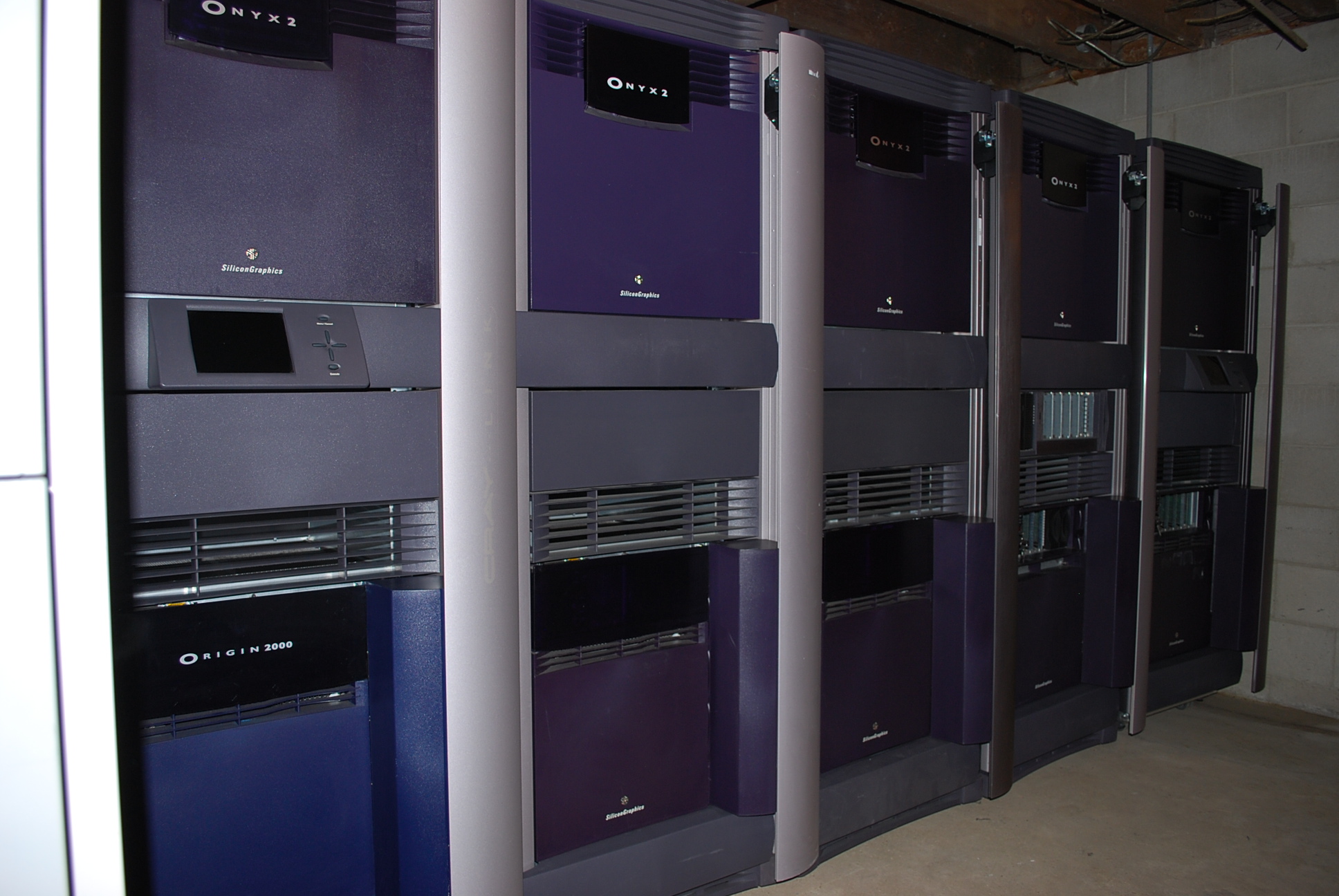
The SGI Onyx2 was the follow-on machine from the original Onyx system, introduced in 1996 and
end-of-lifed in 2003. Released together with the Origin 2000, the systems share a large
percentage of their components, making the range a cost-effective investment for SGI.
The primary shift in thinking on the Onyx2 series was migrating from a single powerhouse of
graphics and processing power in the form of a standalone rack, as in the 'Terminator' Onyx 10k
system, to a newly designed expandable series of machines. The Onyx2's base unit was, again,
the desk side system. This unit was available with two processor slots (up to four processors)
and a four-slot graphics subsystem (of which at least three must be populated for the system
to run). Additionally it came with an IO6G I/O module (containing SCSI, keyboard, mouse, ethernet
ports, and so on), plus six XIO slots, five standard width, one double wide.
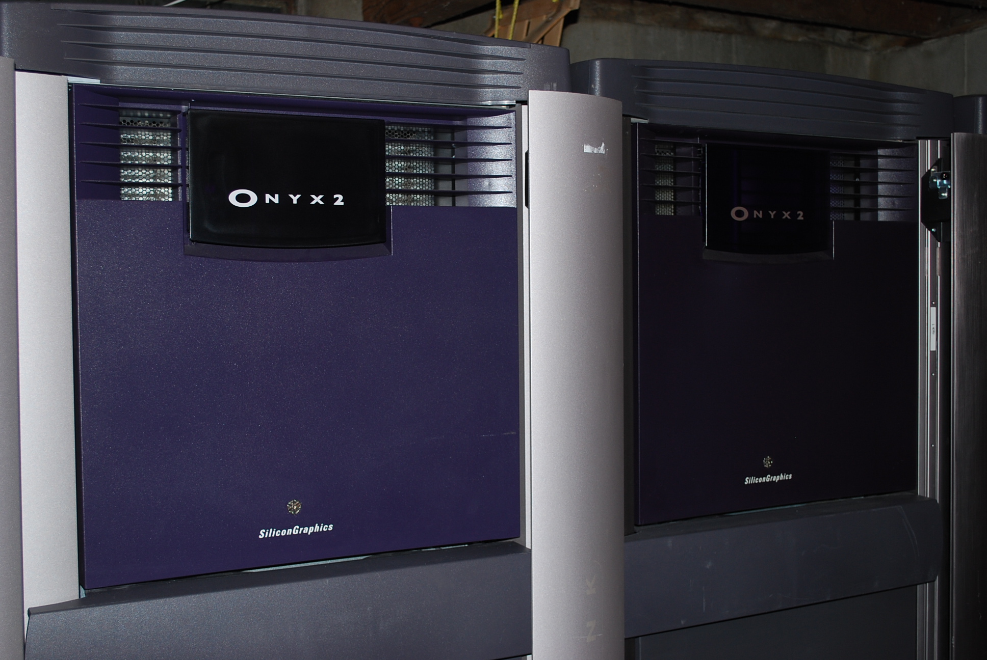
The racked unit consisted of two modules, an upper and a lower. The upper module was the
graphics module, containing eleven slots for up-to two graphics pipes. The lower module was
the processor module, incorporating a disk shelf at the front, and four processor board ("node
board") slots, and the IO6G and XIO slots as with the deskside.
Two rack router boards behind the front skin on the processing module.
What made this design powerful was the built-in expandability. Each processor module could
support a pair of "router boards", a high speed data switch. These switches were
interconnected with CrayLink cables, capable of 800Mbps. There were various router designs
("Null" router for a desk-side, "Star" router for a single rack and "Rack" router, supporting
three CrayLink sockets). At maximum configuration each rack had six CrayLink ports. The SGI
manual defined various methods of connecting racks together to ensure the lowest latency between
modules.
When a multi-rack system was connected together they became a single system. IRIX was
capable of clustering the machines utilising a NUMA architecture - each processor used its
local memory for storage, but was capable of reading memory of remote processors. For large
installations you needed to use 'directory memory', which recorded what was where in the
system's distributed memory.
This design is significant because it made expanding the
number of graphic pipes on a system as simple as adding another rack and it all just
worked.


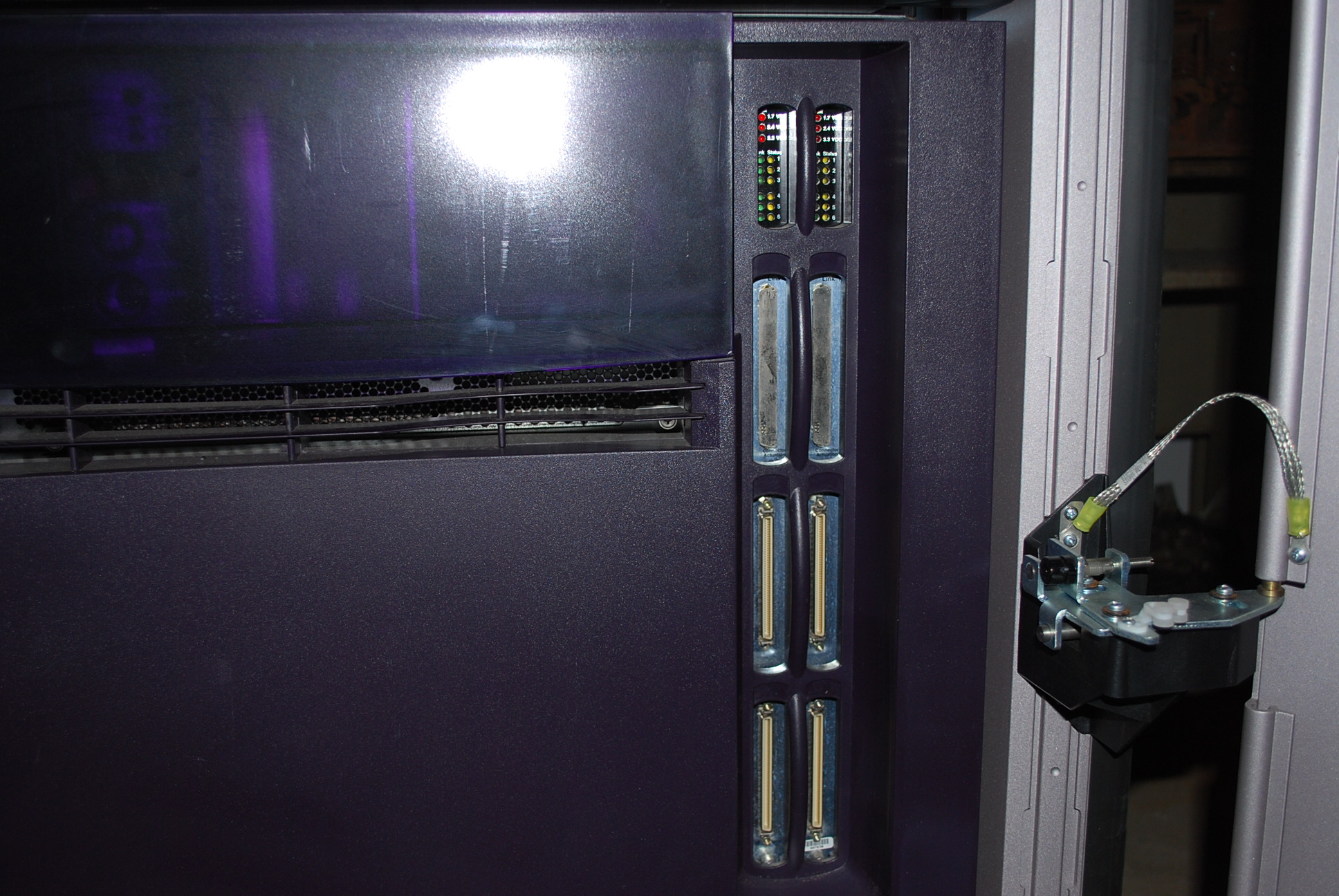
Graphics module skins, rear card cage showing a single pipe and the CrossTown
card, close up of the additional ports on the DG, six of the eight 13W3 connectors (with
cabling attached).
The graphics system consisted of a Geometry Engine, one or more Raster Managers and a Display
Generator. The GE took the data from the system, pushed it through the RMs which had scads
of texture memory, and then fed it into the DG which took the processings from the previous
boards and produced a video signal. The base DG had two 13W3 SGI video ports, the larger came
with eight video ports, plus the standard array of SVideo/composite/GenLock ports and so on.
A graphics pipe required at least one RM card, but you could use up to four to increase their
processing power.
In the centre of the graphics module was a CrossTown board. This effectively extended the bus signals
to a connector on their face, allowing the bus to be joined with the processing module. The CrossTown
board supported two KTOWN ports. These cables were very similar to CrayLink cables and went to an
XTOWN XIO card in the processing module. You required one connection per graphics pipe, so a
machine with a single pipe used only a single CrossTown cable.
The CrossTown board was mounted to the left-of-centre in the module. Boards to the right of the module
was pipe0, supporting up to four RMs. The pipe1, to the left, had less slots, supporting up to two
RMs.
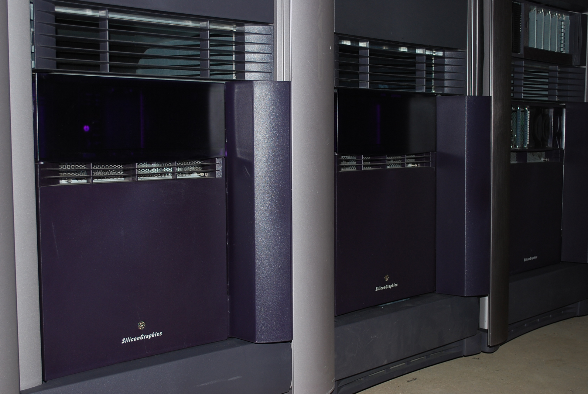

Front skins of the processing module, rear view of the module - node boards on the left, XIO slots to the right, with the IO6G in the top-left slot of the XIO slots.
The processing module, as mentioned, could support up to four node boards. Each board housed two processors and two banks of RAM. Each processor had access to its 'own' bank of RAM - these were simply extensions on the NUMA architecture and did not SMP in any way. They were two isolated processing systems on a single node board.

MMSC in the rear of the unit - the cables go to the modules to tell them to
power on, and the display at the front of the rack.
System initialisation was controlled by either an MSC or MMSC. The MSC was mounted in the front
of a module and managed system power on. This unit had a small ten character display
and a key. Turn the key to 'ON', the system powered up. This worked for a deskside and could be
used to bring up a single-rack system by powering the graphics module up first, and then
bringing the processing module online.
For a multi-rack system some more logic had to be applied. The MMSC, or MultiModule System Controller,
was a small computer (in fact a 486) mounted in the upper-rear of the rack. Each MMSC was connected
to each other via ethernet (a hub was required for more than two-rack setups) and at least one system
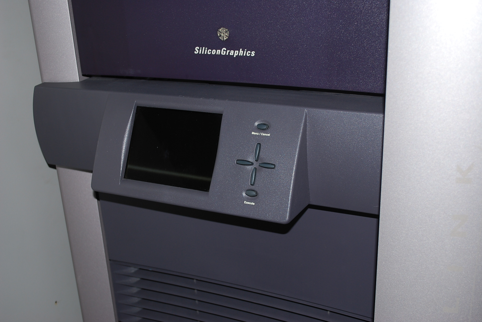
had to have an MMSC display. This display was mounted to the front of the rack and had a 6" LCD
panel and some controlling buttons.
To bring up a multi-rack system each MSC for each module was set to the "StandBy" setting.
The MMSC, which is powered from the rack's PDU and has its own power supply, was then
instructed to power the whole cluster up from the display controller. Each MMSC in the chain
was sequentially told to bring its rack up, with a delay to ensure no breakers were popped
due to the start-up power spike, and then when all racks were powered on a general reset was
sent and the system was ready. IRIX would then boot on whichever rack was defined as the
master and as IRIX came up, would find each rack connected via CrayLinks.
It was possible to run more than one graphics module from a single processor module. Such a configuration was called a RealityMonster. In this setup more than one graphics pipe would work on generating a single video channel. The base setup for this was a triple-rack configuration, with graphics modules in the upper and lower bays of the outer racks, and two processing modules contained within the centre rack.
Part two: